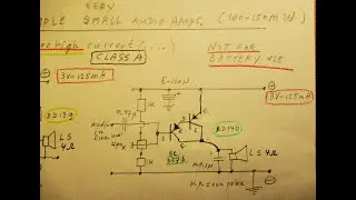
Two too simple 150 mW class A audio amps with 2 transistors, usable on 3 Volt at 125 mA constant
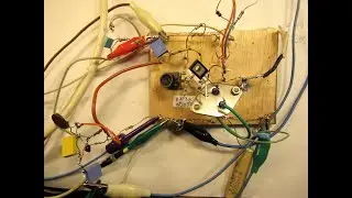
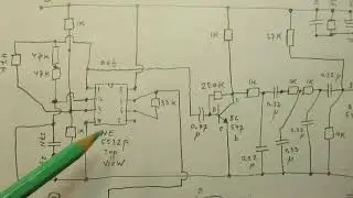
Please read the description first. Two circuits of Class A amplifiers, each made with only 2 transistors, made for (say) 150 mW (Milliwatt) audio out.
Not suitable for battery use, they take a too high constant current.
Next video about a say 500 mW Class A audio amp (4 nov. 2024) is here • Finding out a 0.5 Watt Class A audio ampli...
Remarks & more info about this (now) video:
I uploaded today 27 Oct. 2024 the same video, but with a flaw. One of my followers attended me on that flaw, so I made this new video. Thanks to Ingus Silincs, he attended me.
His YT channel is here / @ingussilins6330
Thus I had to make a new video about the same subject.
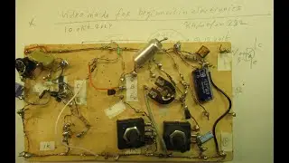
By the way: the circuit on the board was OK, also earlier, there was only a flaw in the drawing. Sorry for that, remove that video. Only the PNP version was not properly drawn.
• Music (now) is copyright free, e.g. “In Albany New York”, from “the 126 ers”.
• The sound that you hear is, in reality, not very strong, somewhat flattered due to the good quality of my camera. Enough (100 mW-150 mW) for background music in a silent room.
• The amplifier input is connected to the headphone output of an (old) handy telephone. That level is, in general, quite fierce. But I am sure it will also work when connected to a line level audio source (say 0,8 Volt AC ).
• Connecting this circuit to the headphone output of a smartphone or MP3 Player comes with risks (!). This is a DISCLAIMER. Reason: the headphone output of MP3 players or smartphones is sometimes not connected to ground/mass. Could also be (+) or “floating”. To be sure you can use (also) a capacitor in the order of 0,47 uF/100 V (non polar) in the “earth/mass” wire to the circuit. Could be that these circuits, in that case, do not work properly.
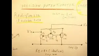
• Set the pureness of the sound with that 470 K trimmer
• Look at this circuit as an experiment, to get an idea about the use of NPN and PNP transistors c.q. “Darlingtons” and/or to make something simple that works quite good. I also have fallen in this "trap" (how NPN's and PNP's can work) in my first video.
Drawbacks of the circuits:
1. Low rendement, too much current at voltage X given a certain amount of audio output
2. In this case only usable on max. 3,2 Volt. The current rises “exponentially” on higher supply voltages, thus risk of transistor burnout
3. The loudspeaker must be able to handle 125 mA, without burning the voice coil out on a short or a longer time
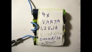
4. Batteries on 3 Volt will be quickly depleted, given that constant current of 125 mA that the circuit takes.
Anyway: it can be useful. The sound is “nice” and not more than that. With a big loudspeaker box even more nice. Try, test, experiment!
My You Tube channel trailer is here: • Radiofun232 on YouTube. Updated monthly.
I cannot "immerse" my channel trailer into the textbox (made via Word) directly, when uploading a video, because of shadow banning of Google/YT. That started in 2020 (when I was critical about the CVD jabs) and still works up until now (2024). Google/YT does not want you to visit my Channel trailer.
Whatever that may be: type on my Channel Trailer the keywords that you like (e.g. radio/audio/amplifiers/test/filter/) into the “looking glass” = search function” and give “enter”. Via that you can find specific video’s (under the say 1500 published).
When you search, search always “NEWEST FIRST” to get the right overview.
You can also search via the “looking glass” on my Channel trailer via keywords like ”audio”, “radio”, “amplifier”, “filter”, “Shortwave”, “transistor”, “FET”, “oscillator”, “generator”, “switch”, “schmitt trigger” etc; so the electronic subject you are interested in.
My books about electronics & analog radio technology are available via the website of "LULU”, search for author “Ko Tilman” there.
Direct link (nov 2024) is here https://www.lulu.com/search?adult_aud...
I keep all my YT videos constant actual, so the original video’s with the most recent information are always on YouTube. Search there, and avoid my circuits that are republished, re-arranged, re-edited on other websites, giving not probable re-wiring, etc. Some persons try to find gold via my circuits. I take distance from all these fake claims. Upload 27 October 2024.
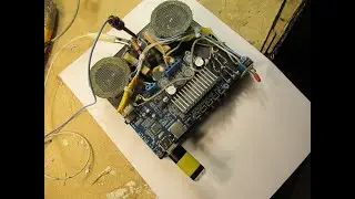
NB: you can make it, of course, for stereo. Will take 2 x 125 mA=250mA. Only 4 transistors used, in that case. Sound will be very small, but, on the other hand, quite nice when playing music in a silent living room on such a low amplitude, in case of stereo say 2 x 100 Milliwatt. Test & try, it could give an enormous satisfaction, especially with loudspeaker boxes that have a high effenciency, say good quality broadband loudspeakers (50 Hz-14 KC). Could be made with 2 x the loudspeaker that I show in this video: with its rubber "ring" and its dome, the dome made for freq. above 10 KC.