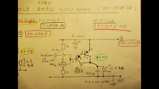
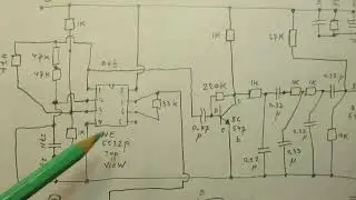
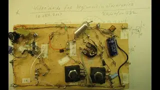
Beginners 1 transistor audio or HF amplifier. The grounded emitter schematic, 2 times showed
Please read the description first. Everything is showed and told. Thus I don’t have to elaborate more.
Two 1 transistor circuits (GE-circuits = grounded emitter circuits, they have the best properties in voltage amplification) are showed that can help you.
For audio amplifiers (20 Hz-20 KC) and also for HF applications.
In these HF applications the input and output capacitors have to be made (very) small: 100 pF – 10000 pF. Perhaps even smaller (frequency dependent). For audio: 470 N (=0.47 uF, non polar!, thus no electrolytics!) as input and output capacitor always works OK.
Say an application can be (for audio): to make a simple microphone amplifier, a pickup amplifier, or any other audio pre-amplifier. Via a 1 uF (n.p. capacitor) at its entrance, and a 1 uF (non polar) capacitor at its output (schematic is in the video).
For audio: all frequencies with that non polar cap. of 1 uF (or 470 N cap = 0.47 uF non polar cap) can pass and will be amplified properly.
Not enough (audio) amplification? Swith 2 of these 1 transistor stages in a row (second schematic, because in that case you can "tame" the amplification via that potmeter in the emitter lead, that is very important to not "overdrive" the signal(s) where sinewave are turned into squarewaves (= clipping).
Use non-polar caps of (say 0.47 uF, for audio) to couple that first stage to the second stage.
Electrolytics (when used as coupling/separation capacitors) wil deteriorate on the longer term. And 470 N (0.47 uf non polar) is good enough to transport the whole audio range, from 50 Hertz to (say) 20 KC in and out.
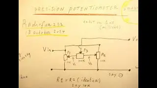
Circuit (1) amplifies (max). 300 x (it depends on the natural amplification of the used NPN transistor, here a BC 547 b, test that amplification factor via a transistor tester. Could also be lower value, 100 or 200.
Circuit (2) the Audio or HF amplification is set by the 1 K potmeter in the emitter lead + its paralled capacitor (more info in the video). So you can "align", preventing the clipping of audio signals (clipping = audio distortion). In circuit (1) that (clipping prevention) can only be done by bringing the supply voltage down, say to the 3-6 Volt region. Can be done with a resistor voltage divider, b.t.w.
Very substantial amplification can be reached, by turning that 1 K potentiometer (with its paralled cap. In the order of 100 uF-50 NF) in its emitter lead.
My You Tube channel trailer is here: • Radiofun232 on YouTube. Updated monthly.
Type there the keywords that you like (e.g. radio/audio/amplifiers/test/filter/) in the “looking glass” = search function” and give “enter”. Via that you can find specific video’s (under the say 1500 published).
When you search, search always “NEWEST FIRST” to get the right overview.
You can also search via the “looking glass” on my Channel trailer via keywords like ”audio”, “radio”, “amplifier”, “filter”, “Shortwave”, “transistor”, “FET”, “oscillator”, “generator”, “switch”, “schmitt trigger” etc; so the electronic subject you are interested in.
My books about electronics & analog radio technology are available via the website of "LULU”, search for author “Ko Tilman” there. Direct link is https://www.lulu.com/search?adult_aud...
I keep all my YT videos constant actual, so the original video’s with the most recent information are always on YouTube. Search there, and avoid my circuits that are republished, re-arranged, re-edited on other websites, giving not probable re-wiring, etc. Some persons try to find gold via my circuits. I take distance from all these fake claims. Upload 10 October 2024.
NB: please note the circuits are "bare", thus no compensation for lifting certain audio bands (somewhere in the 20 Hz-20 KC band) "up" or pressing certain frequencies in the audio band "down". Of course there will be certain effects in the audio band, when turning that 1 K potmeter in the emitter lead of circuit 2, when you listen to that 1 transistor audio amp or look to its signals via the oscilloscope. Has to do with many things, e.g. how the human ear(s) interpret sound (s).
Always "decouple" (for audio circuits) the 9 Volt or 12 Volt (+) lead) in this way: an electrolytic of 1000 uF, bridged with a 470 K resistor and a 0,1 uF capacitor, between (+) and (-). I mean: especially for audio circuits. For HF circuits this can work good up to 12 MC.
Best idea: use a resistor of 47 Ohm and supply the "decoupling" unit via that, in these cases.
Though for square wave oscillators (not here) this heavy damping in the supply voltage lead can lead to start problems. Strange but true: some square wave oscillators don't want to work when the voltage slowly comes up. More info about that in quite a few vids on my YT Channel. They (can/will) stall.
But here we are talking about audio and HF amplifiers, thus there that is no problem & proper decoupling of the (+) voltage line is key (!). 11 Okt 2024.