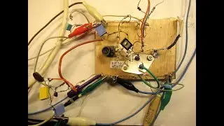
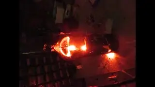
The Astabile Multivibrator can always fool you (happy flickering Christmas lights) schem/demo
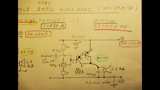
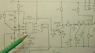
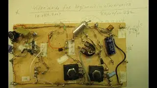
Please read the description first. I used here an Astabile MUVIB, made in a classical way with 2 medium power NPN transistors, the BD 139s, amplification factor approx. 150.
Reason for the use of the BD 139 is that these transistors can handle a quite high C-E current and can dissipate (in the ideal situation) 5 Watt or so. NB: every Silicon transistor with a dissipation of (say) 3 or 5 Watt and a Hfe of (say) 150 can do this job. Say e.g. the 2N2219, it has a good current amplification factor, though that 2N2219 cannot handle so much current, say max 400 mA in practice at say 9 Volt or so.
That dissipation (3-5Watt) could be handy when you have strings of LEDS with many LEDS inserted.
E.g: say: every LED takes 10 mA, 10 of them in a row take 10 x 10 = 100 mA. Always use completely identical LEDS, when you to parallel them in a row.
Of course you can buy also a string of LEDS in a row, say via Ali.
Try to get an idea about how the max. current and voltage must be to make them light up nice.
When testing that (this is a disclaimer): A tiny too high voltage can lead to a destructive current in such a test case of such a string or (in fact) any LED. Be very prudent and always use a power supply via which you can lift up the voltage very precise, say by turning a knob. Changes in the order of 1/10 of a volt are necessary for a good test in these cases.
That is also why power LEDS and paralleled LEDS in a row (in the ideal case, the best case) have to be supplied via a constant current source.
That is not now, here, in this circuit, realized, because it is a fun circuit only using 3 LEDS in a row for each leg.
Controlling current through the LEDS is done here/now via the precise value of the collector resistors, they have to be in this case 0.5 Watt types. Between say 100 Ohm and 47 Ohm.
With many (identical) LEDS in that row, they must be 1 Watt or (perhaps) even 3 Watt types. Test, try, experiment. To get “insight” in e.g. how Ohms law (U=IxR) that works here in practice. B.t.w. always start with a low(er) voltage and make it slowly higher, to see where the circuit starts to work.
My You Tube channel trailer is here: • Radiofun232 on YouTube. Updated monthly.
(btw: I am shadow banned by Google = Youtube and (perhaps) by other actors that take my comments on serious video's on YouTube (social/economic issues, regarding us all, especially within the EU and Dutch politics, the Ukraine war and more) down. They make my comments not visible and even delete them (!). It is true. 13 oct. 2024).
When you search, search always “NEWEST FIRST” to get the right overview. You can also search via the “looking glass” on my Channel trailer via keywords like ”audio”, “radio”, “amplifier”, “filter”, “Shortwave”, “transistor”, “FET”, “oscillator”, “generator”, “switch”, “schmitt trigger” etc; so the electronic subject you are interested in.
My books about electronics & analog radio technology are available via the website of "LULU”, search for author “Ko Tilman” there. https://www.lulu.com/search?adult_aud...
DIRECT link is https://www.lulu.com/search?adult_aud...
I keep all my YT videos constant actual, so the original video’s with the most recent information are always on YouTube.
Search there, and avoid my circuits that are republished, re-arranged, re-edited on other websites, giving not probable re-wiring, etc. Some persons try to find gold via my circuits. I take distance from all these fake claims. I cannot help that these things happen. Upload 13 October 2024.
Tried to make a simple “Christmas” light, but encountered the classical A-Stabile MUVIB problems. Many times I have payed attention to these things, on my YT Channel, anyway. It works, now, on 12 Volt. Wish you luck an a happy autumn and december!