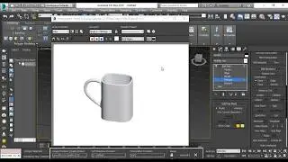
Mastering Editable Poly | Making Mug from a box Using Editable poly | 3ds Max
A polygon is a closed sequence of three or more edges connected by a surface. Polygons provide the renderable surface of editable poly objects.
• Select an editable poly object. Modify panel Selection rollout Polygon or Element
• Select an editable poly object. Modify panel Modifier List display Expand Edit Poly. Polygon/Element
• Select an editable poly object. Quad menu Tools 1 quadrant Polygon or Element
At the Editable Poly (Polygon) sub-object level, you can select single and multiple polygons and transform them using standard methods. At the Element sub-object level you can select and edit groups of contiguous polygons. For further distinctions between polygon and element, see Editable Poly Selection rollout. This topic covers the Edit Polygons/Elements rollout and Edit Geometry rollout functions for these sub-object types; for other controls, see Editable Poly.
Interface
Selection rollout
See Editable Poly Selection rollout for information on the Selection rollout settings.
Edit Polygons/Elements rollout
Insert Vertex
Lets you subdivide polygons manually. Applies to polygons, even if at the element sub-object level.
After turning on Insert Vertex, click a polygon to add a vertex at that location. You can continue subdividing polygons as long as the command is active.
To stop inserting vertices, right-click in the viewport, or click Insert Vertex again to turn it off.
Extrude
Lets you perform manual extrusion via direct manipulation in the viewport. Click this button, and then drag vertically on any polygon to extrude it.
Extruding polygons moves them along a normal and creates new polygons that form the sides of the extrusion, connecting the selection to the object.
Outline
Lets you increase or decrease the outside edge of each contiguous group of selected polygons.
Outline is often used after an extrusion or bevel to adjust the size of the extruded faces. It doesn't scale the polygons; only changes the size of the outer edge. For example, in the following illustration, note that the sizes of the inner polygons remain constant.
Extruded polygons (top), outline expanded (middle), outline reduced (bottom)
.
Note that inner polygons do not change size.
• Outline Settings Opens the Outline Polygons caddy, which lets you perform outlining by a numeric setting.
For details on using the caddy controls, see The Caddy Interface.
Bevel
Lets you perform manual beveling via direct manipulation in the viewport. Click this button, and then drag vertically on any polygon to extrude it. Release the mouse button and then move the mouse vertically to outline the extrusion. Click to finish.
• When over a selected polygon, the mouse cursor changes to a Bevel cursor.
• With multiple polygons selected, dragging on any one bevels all selected polygons equally.
• You can drag other polygons in turn to bevel them while the Bevel button is active. Click Bevel again or right-click to end the operation.
Polygon beveled outward (left) and inward (right)
• Bevel Settings Opens the Bevel caddy, which lets you perform beveling via interactive manipulation.
If you click this button after performing a bevel, the same bevel is performed on the current selection as a preview and the dialog opens with the same settings used for the previous bevel.
Inset
If you click this button after performing a manual inset, the same inset is performed on the current selection as a preview and the dialog opens with Inset Amount set to the amount of the last manual inset.
Tip: You can also interactively inset polygons directly in the viewport. To do this, select the Move transform tool and then hold Shift as you drag the polygon.
Bridge
Connects two polygons or polygon selections on an object with a polygon “bridge.” There are two ways to use Bridge in Direct Manipulation mode (that is, without opening the Bridge Settings dialog):
Using Bridge at the Polygon level
Note: Bridge always creates a straight-line connection between polygon pairs. To make the bridge connection follow a contour, apply modeling tools as appropriate after creating the bridge. For example, bridge two polygons, and then use Bend.
• Bridge Settings Opens the Bridge Polygons caddy, which lets you connect pairs of polygon selections via interactive manipulation.
• Hinge Settings Opens the Hinge From Edge caddy, which lets you hinge polygons via interactive manipulation.
If you click this button after performing a manual hinge, the dialog opens with Angle set to the extent of the last manual hinge.
Extrude Along Spline
Extrudes the current selection along a spline.
Set ID
Lets you assign a particular material ID number to selected polygons for use with multi/sub-object materials and other applications. Use the spinner or enter the number from the keyboard. The total number of available IDs is 65,535.