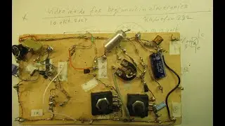
Astabile Multivibrator with FETS, not ideal, 30 Hz-12 KC schematic and demo, fun for experiments
Please read the description first. Circuit of a Astabile Multivibrator that can work between 30 Hertz and 12 KC. Correction: the pin connections in the drawing and the thumbnail are not (!) OK... Also in practice I reversed Drain and Source. Though it worked. Also strange. Perhaps that was the reason of the poor functioning. Thanks @kd5ozy !
Re-tested it on 23 June 2024: it works in both cases, whether Drain and Source are reversed, or not. In both cases with the same issues.
Making such a circuit with FETS is not (!….) easy. I did quite a few experiments to finally find this circuit that works (somewhat, but in my opinion not ideal, given the low frequency range, max. 12 KC, and its critical supply voltage). Perhaps important: I used MOSFETS, they have often or in general a quite high capacitance at their Gates, if so that will limit the maximum frequency that could be reached. Could be a reason...
With BJT transistors such a circuit (Astable Muvib) has a high success factor, say 80 -90 % or so.
Say it “always” wants to work, with 2 BJT transistors, 2 caps and 4 resistors.
Many circuits with that setup are on my YT Channel. You can find them via the “looking glass” (= search option) on my Channel Trailer, “Radiofun232 on YouTube”. Type there searchwords like “multivibrator” or “Astable” or “A Stabile multivibrator.
With BJT transistors this circuit can work on a broad range of voltages, going from (say) 0,8 Volt to 24 Volt or even higher.
With this FET circuit that is not (!) the case, the voltage where it wants to work is very critical (bandwith of 1,5 Volt) and it also depends (as far as I could see) somewhat on the generated frequency.
Combined with the critical setting of the second 470 K potentiometer in the circuit, anyway.
The frequency where it works is set by the 2 capacitors. Their values set the frequency band where it works. The duty cycle can be set via (different or the same) values of these capacitors.
The duty cycle also depends on the setting of the second 470 K potentiometer, thus the one going to the second IRF 830 FET.
With 2 X the BF 256 A (small signal N-FET) it did not work, but with 1 X BF 256 A (as first transistor) and 1 X IRF 830 (as second transistor) it worked.
Room for many experiments and many hours of fun! To get this circuit to work better and/or adapt it to your personal needs and idea’s for a certain electronic application!
Better and easier Astabile Muvib oscillators made with normal transistors (BJT circuits) can be found via the Channel Trailer on my YT Channel.
My You Tube channel trailer is here: • Radiofun232 on YouTube. Updated monthly.
When you search, search always “NEWEST FIRST” to get the right overview.
You can (thus) search via the “looking glass” on my Channel trailer. Alsof or electronic circuits )audio & radio & test equipment). Via keywords like ”audio”, “radio”, “amplifier”, “filter”, “Shortwave”, “transistor”, “FET”, “oscillator”, “generator”, “switch”, “schmitt trigger” etc; thus the electronic subject you are interested in.
My books about electronics & analog radio technology are available via the website of "LULU”, search for author “Ko Tilman” there.
Direct link to these books (6 nov 2024) is here https://www.lulu.com/search?adult_aud...
I keep all my YT videos constant actual, so the original video’s with the most recent information are always on YouTube. Search there, and avoid my circuits that are republished, re-arranged, re-edited on other websites, giving not probable re-wiring, etc. Some persons try to find gold via my circuits. I take distance from all these fake claims. Upload 22 June 2024.