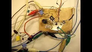
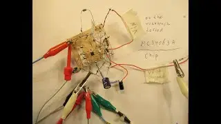
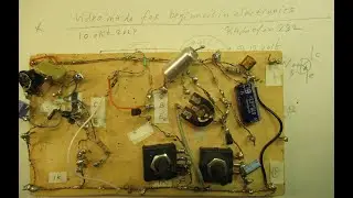
Testing the LM 317 Voltage Regulator, giving it a hard test but it works OK. Schematic & demo.
Please read the description first. In this video I tested the LM317 Voltage regulator and concluded that it works very properly.
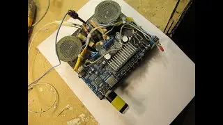
For higher output currents (say above 100 mA): use a heatsink. That (heatsink) depends also on the Voltage drop in-out. Smaller Voltage drops: less heat inside the chip.
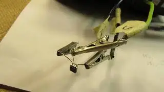
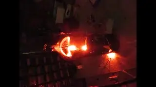
In my case (say 300 mA out to the 2 incandescent lamps made for 12 V and 3 or 5 Watt, switched in series, input Voltage 25 Volt and even on 18 Volt) the heatsink got extremely hot. But that was, in a certain way, an "overdone" output current, though the LM 317 withstanded that heavy test (!).
Thus the LM317 Chip was not damaged even on that overdone output current. That is a very good result.
By the way: I only tested that setup during 1 hour, anyway, do your own tests.
Best idea in electronics is to keep the heat of your semiconductors in the “warm” (I talk about Silicium transistors, not about Germanium transistors) range and not in the “hot” range.
Though even in the 1970’s-1980’s there were special power transistors developed that could handle the heat of 150 degrees Celsius for a very long time, say it belonged to their normal lifespan.
Thanks to Barry Blod, he showed me a few weeks ago a schematic of an audio amplifier where these transistors were used.
These (BJT) transistors did not suffer from the so called “second breakdown effect”. Thanks, Barry.
Whatever that all may be: with “hand warm” semiconductors in your (home brew) electronic circuit you know that your semiconductors will have an eternal life.
So only mechanical problems (switches, switch contacts, moving parts, etc.) can cause problems on the long or longer term, thus not the semiconductors.
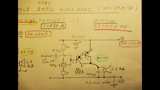
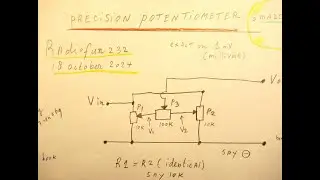
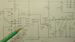
Idea of the video: with that LM317 Constant Voltage Regulator the output voltage, set via that 2K5 or 5 K potentiometer and the 470 Ohm resistor (they together act as a variable voltage divider to the adjust pin of the chip) an output voltage can be set that does not change when the current goes up substantially at the output pin of the Chip.
That was demonstrated in this video.
The “extra” components (10 uF cap./1M resistor/100N cap. at the input and output of the Chip) are there for (say) “stability” (decoupling).
The book/magazine that I talk about is from “National Semiconductors”, of the 1970's or 1980's (still actual by the way, now in 2023...) the pages about the LM 317.
A lot more information is in that book about all the properties of this chip. To be precise: on page 1 -15 of this book, pages 1-15 to 1-22. The book shows many applications of this LM317 Chip, not only used as a (simple) Voltage Regulator.
My You Tube channel trailer is here: • Radiofun232 on YouTube. Updated monthly.
When you search, search always “NEWEST FIRST” to get the right overview.
You can also search via the “looking glass” on my Channel trailer via keywords like ”audio”, “radio”, “amplifier”, “filter”, “Shortwave”, “transistor”, “FET”, “oscillator”, “generator”, “switch”, “schmitt trigger” etc; so the electronic subject you are interested in.
My books about electronics & analog radio technology are available via the website of "LULU”, search for author “Ko Tilman” there.
https://www.lulu.com/search?adult_aud...
I keep all my YT videos constant actual, so the original video’s with the most recent information are always on YouTube. Search there, and avoid my circuits that are republished, re-arranged, re-edited on other websites, giving not probable re-wiring, etc. Some persons try to find gold via my circuits. I take distance from all these fake claims. I cannot help that these things happen. Upload 21 December 2023. Merry X-mas, by the way!