Making a very simple oscilloscope Pt 10: a VLOG & sawtooth generator & schematic update & more
Please read the description/textbox first. This is only a VLOG though I show 2 working schematics.
The development will be postponed for a certain time because I have "blown up" my sine wave generator (1Hz-10MC) on 2 nov 2022. It has to be repaired first.
FINAL VIDEO about the oscilloscope (5 Dec 2022) is here • Making a very simple oscilloscope Pt....
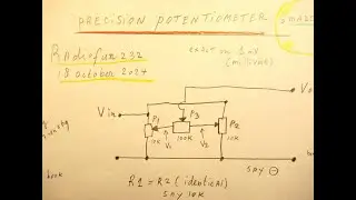
One schematic is from this book: “Elektronica” by P.J. van Engelshoven, part 2b, issued by J.B. Wolters, Groningen, the Netherlands, 1966, page 241-242. No ISBN number found.
Issue for the future will be to make a sawtooth generator + a horizontal amplifier that is able to move the dot on the oscilloscope screen fierce.
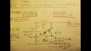
At the same time a vert. deflection amplif. must work, it can work between (say) 1 Hertz and (say, in this case) 40 KC, it has to drive the vertical plates in the order of AC 40 Volts or so. Could be a kind of audio amplifier on 40-60 Volts, to drive the vertical plates. And triggering must be made.
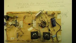
First circuit of the CRT (complete overview) is showed (25 okt. 2022).
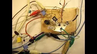
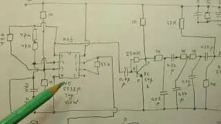
Second CRT circuit is showed now (31 october 2022) with the easy sawtooth generator.
It was made with the BD 139 NPN & the BD 140 PNP. It could move the dot for a good part completely from the left to the right, but it lacked (some/good) linearity, thus I had to (you can) push that non-linearity of the “CRT dot” out of the screen (to the right) by using the hor-move potentiometers.
Thus looking on the more linear part of the (not perfect) sawtooth wave. Also the potentiometer of 5 K inside of the 2 transistor Sawtooth generator will help to push that CRT dot out of the face of the CRT tube (line shift).
That simple 2 transistor Sawtooth/time base worked in a certain way (schematic showed), but every capacitance on the output of that 2 transistor Sawtooth generator (be it from the plates inside the CRT tube, or the coupling capacitor that had to send in the frequency/voltage to the horizontal plates, say 220 N or 1 uF) had an effect on the sawtooth wave frequency.
Thus on the time base + the dot on the CRT screen. Thus: effects on frequency change and dot-movement.
Thus: the value of the coupling capacitor out of this simple 2 transistor sawtooth generator that is going to the horizontal plates effects the frequency and the driver voltage to the hor. plates of the CRT.
I will publish a better circuit of this all in the future.
A circuit that is able to push the dot fierce from the left to the right in a frequency band of 1 Hertz to 40 KC.
My You Tube channel trailer is here: • Radiofun232 on YouTube. Updated month... When you search, search always “NEWEST FIRST” to get the right overview.
You can also search via the “looking glass” on my Channel trailer via keywords like ”audio”, “radio”, “amplifier”, “filter”, “Shortwave”, “transistor”, “FET”, “oscillator”, “generator”, “switch”, “schmitt trigger” etc; so the electronic subject you are interested in.
My books about electronics & analog radio technology are available via the website of "LULU”, search for author “Ko Tilman” there.
https://www.lulu.com/search?adult_aud...
I keep all my YT videos constant actual, so the original video’s with the most recent information are always on YouTube. Search there, and avoid my circuits that are republished, re-arranged, re-edited on other websites, giving not probable re-wiring, etc. I cannot help that these things happen. Upload 31 october 2022.
Other videos in this Simple Oscilloscope series:
Part 1: • High Voltage circuit 1KV- 4KV for an ... (about HV circuits on 16-18 KC, made with a line transformer on 16 KC, principles & schematic, first idea’s 1 october 2022)
Part 2 : • Making a very simple oscilloscope Par... (first setup, some common things to tell about a CRT circuit, video named part 2, on 5 october 2022)
Part 3 : • Making a very simple oscilloscope Par... (shielding the tube for EM influences, common things, 6 october 2022)
Part 4: • Making a very simple oscilloscope Pt.... (schematic of a HV generator on 16-18 KC, with a line CRT transformer, 16 KC, made with 2 x 2955 end transistors, A stable Multivibrator, schematic, 13 october 2022)
Part 5: • Making a very simple oscilloscope Pt ... (showing some solutions, High Voltage say 380 V DC with a few simple mains transformers, working on 50 Hz or 60 Hz, 15 october 2022)
Part 6: • Making a very simple oscilloscope Pt ... (about the filament voltage circuit, 6 V at 300 mA, 18 oct. 2022.
Part 6 or so: the 6.3 Volt at 300 mA filament voltage • Making a very simple oscilloscope Pt ...
Part 7: proper connections of the brightness & focus grid in the CRT • Making a very simple oscilloscope Pt ...
Part 8: VLOG, moving the dots & lines on the CRT screen • Making a very simple oscilloscope Pt ...
Part 9: definite schematic about the internal voltages inside the DG 7-32 CRT; brightness, focus, etc.
Sawtooth generator of the earlier YT video (oct 2022) is here • What to do with a sawtooth generator ...
Part 10: this video (31 oct 2022).
Wish you luck & success!


![CORRUPTION TIME [0.6.0] [Incutia] باللغة العربية PT ESPAÑOL ANDROID Y PC](https://images.mixrolikus.cc/video/fgo4c0crog0)