Rebuilding/downgrading a high Q Farnell Sine wave oscillator VLOG 3: FET oscill (130KC-12MC) schema.
Please read the description/textbox first.
VLOG 3. Rebuilding/downgrading the High Q Farnell sine wave generator to a simple sine wave test oscillator circuit for (aim) 100 KC-12MC. Practical, after first tests: 130 KC-12 MC.
Best schematic (22 feb. 2023) with more info in the description is here
• VLOG 6: Sine Wave oscillator 130 KC-8...
IMPORTANT correction (10 feb. 2023): when you want to go to the lowest frequency band (130 KC) the extra capacitor to be switched in (parallel to the coil in the source lead) must NOT be 1 N (1000 pF) but 10 N (10000 pF). Feel free to experiment with the value of this capacitor, perhaps with a higher value than 10 N (and a coil with an inductance higher then 3,9 milliHenry you can even get to 50 KC. Could be, try it.
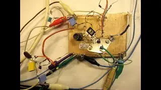
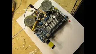
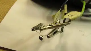
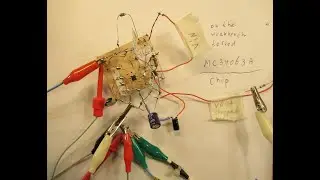
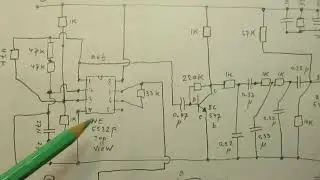
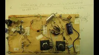
I show the FET oscillator that I am going to use. I pre-tested this setup/schematic and could get to frequencies between 130 KC and 12 MC. Schematic is showed in this video.
In most cases an extremely pure sine wave is there (3 MC-10MC), though on other frequencies sometimes with "bibbers" in the waveform. It depends on the coil quality: neat & properly wound or not. Sloppy wound coils give (in general) "bibbers" in the waveform, but there are more reasons for that. It needs some more (experimental) study, though these are the principles.
The BF 256A is a FET that is still now (2023) available on the market. The BF 245 A,B, or C is obsolete now.
Coils of different “makes” (between Gate and Ground, paralleled with a tuning capacitor of 10 PF-1000 pF or a fixed value capacitor between 10 pF and 1000 pF (=1N) can/will work with this oscillator.
But: for the lower frequencies (130 KC-1MC) you must connect the capacitor of 1 N (=1000 pF) paralleled to the (mini) kind of "choke coil". It consists of 250-300 windings on a form of 3-5 mm diameter, no ferrite inside, thus a simple plastic tube. That small 300 wdg. coil goes from the Source of the FET to ground, here that is (-), minus.
It is connected parallel to the 100 pF capacitor that is already there. That 100 pF capacitor that is already there is a kind of standard/minimum value to make the oscillator work, at least from 3 MC and higher.
Please note: There is also a 220 pF capacitor soldered between the Source and the Gate of the BF 256A FET.
You can also use a BF 245 A,B, or C, in this schematic, though they are obsolete and perhaps hard to find.
Important: this FET oscillator sends its HF sine wave signal out via a 68 pF capacitor, out of the Source lead.
This 1 transistor FET circuit cannot (not…) be “loaded” to much on its output, because the oscillation surely will stop in that case.
Say the output resistance/impedance is in the 1 Mega Ohm order.
So it needs a buffer stage, that “decouples” the output of this FET oscillator. Such a buffer stage makes the 130 KC-12 MC oscillator not sensible to a too low output resistance/impedance. So that it does not stop oscillating and keeps on working, even when there is a very low output impedance/resistance.
That will be the next stage in this project: developing & testing the buffer stage on frequencies between 130 KC and 12 MC.
First video/VLOG: • Rebuilding/downgrading a high Q Farne...
Second video/VLOG: • Rebuilding/downgrading a High Q Farne...
My You Tube channel trailer is here: • Radiofun232 on YouTube. Updated month... When you search, search always “NEWEST FIRST” to get the right overview. You can also search via the “looking glass” on my Channel trailer via keywords like ”audio”, “radio”, “amplifier”, “filter”, “Shortwave”, “transistor”, “FET”, “oscillator”, “generator”, “switch”, “schmitt trigger” etc; so the electronic subject you are interested in.
My books about electronics & analog radio technology are available via the website of "LULU”, search for author “Ko Tilman” there.
https://www.lulu.com/search?adult_aud...
I keep all my YT videos constant actual, so the original video’s with the most recent information are always on YouTube. Search there, and avoid my circuits that are republished, re-arranged, re-edited on other websites, giving not probable re-wiring, etc.
Some persons try to find gold via my circuits. I take distance from all these fake claims. I cannot help that these things happen. Upload 8 February 2023.