Making a very simple oscilloscope Part 3: aligning the CRT tube and shielding it for EM influences
Making a very simple oscilloscope, Part 3. Please read the description/textbox first.
First video about this project is here (3 oct 2022):
• Power supply 500 Volt DC static Volta...
Second video about this project (5 October 2022) is here
• Making a very simple oscilloscope Par...
Next video (first exp. sawtooth generator, 8 Oct 2022) • What to do with a sawtooth generator ...
CORRECTION/UPDATE (8 October 2022) TO all the earlier video's: the deflection voltage to the horizontal and vertical platse is not in the 10 Volt order, but in the 150 V-200 Volt order, to make a line from left to right over (say) 7 cm of screen width. Sorry, I misunderstood the datasheet. Will (thus) take more time to make the deflection amplifiers, anyway.
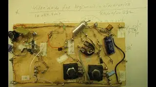
Now I show how the CRT tube is fixed and shielded via a cone-like piece of tin plate. It will shield it against E.M. Influences.
I also show how the tube is aligned, compared to the round opening of the (shielded) front, to which the tin plate cone is soldered.
To give that tin plate cone (where the CRT tube slides into) a perfect connection to the mass.
Here that mass will be on (0), the zero, because I will connect the (+) of the HV generator (500 Volt to the anode of the CRT) to ground and to the anode. Ground is then O, Mass.
The electrons (negative elements in terms of physics) will flow from the cathode via the brightness grid (Wehnelt cylinder) and the focus grid (not a grid but a tube like structure, watch the video) to ground, because ground is positive.
That will be a first test. The best idea of that option is that the (static) deflection plates of this electrostatic deflection CRT tube, are not on that high anode potential. Strange? That was an issue on earlier experiments.
Thus by making it more easy to work with them and drive these plates with voltages: time base generator (= sawtooth generator) and also the vertical deflection plates.
Perhaps more to come and show in the future about this circuit, at least I have showed the bare essentials, about how to make it.
There are some old video’s regarding the simple oscilloscopes that I made in the past. When you are interested they are here:
Earlier video’s • home brew oscilloscope (video about the homebrew 2 Hz-40 KC oscilloscope) And: • Oscilloscope: how to make a very basi... That second circuit was an experiment that was halfway successful.
In my books I have showed 2 succesful cathode ray scope/tv circuits. One with a static deflection (max 40 KC) and one with an electromagnetic deflection (max. 15 KC).
They are in my book “Schematics 3, - transistor switches, generators and cathode ray tube circuits”, available on the LULU website, author Ko Tilman. LULU content number 10469565 or ISBN nr 978-1-4476-1164-6.
Page 32-53: one oscilloscope with static deflection (max. 40 KC) & one oscilloscope with electromagnetic deflection (max 15 KC). Usable to make audio phenomenon visible, say phase relations, or use it as an audioscope to make sound visible on the screen.
My You Tube channel trailer is here: • Radiofun232 on YouTube (updated monthly)
When you search, search always “NEWEST FIRST” to get the right overview. You can also search via the “looking glass” on my Channel trailer via keywords like ”audio”, “radio”, “amplifier”, “filter”, “Shortwave”, “transistor”, “FET”, “oscillator”, “generator”, “switch”, “schmitt trigger” etc; so the electronic subject you are interested in.
My books about electronics & analog radio technology are available via the website of "LULU”, search for author “Ko Tilman” there. https://www.lulu.com/search?adult_aud...
I keep all my YT videos constant actual, so the original video’s with the most recent information are always on YouTube. Search there, and avoid my circuits that are republished, re-arranged, re-edited on other websites, giving not probable re-wiring, etc. Some persons try to find gold via my circuits. I take distance from all these fake claims. I cannot help that these things happen.
Upload 5 October 2022.