Frequency dependent backcoupling & audio filtering (2 transistor demo circuit)
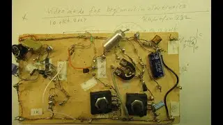
Correction to the video: the date is (of course) 7 march 2019. Sorry for that. Music: In Albany, New York, by the 126 ers (copyright free, good music for audio demo's, they have made more good tracks for that purpose and it is quite relaxing).
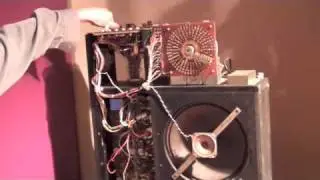
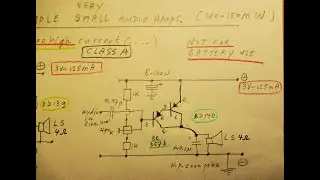
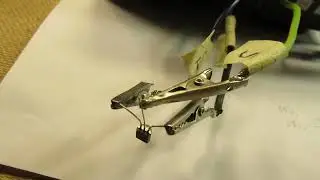
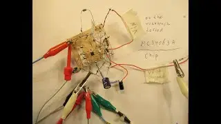
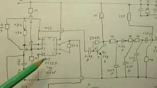
In this video I show the effect of backcoupling an audio signal (out of a CD player, smartphone headphone plug out) back to the input of a 2 transistor audio amplifier via a capacitor. More background information at the end of this textbox.
Every capacitor value gives its own audio effect. It is only a small demo, more info about how to get the sound that you like and want in your living room is in my book “Schematics 2, audio amplifiers and loudspeaker boxes”, available on the Lulu website, author Ko Tilman.
This video only shows the “frequency dependent backcoupling effect” in that 2 transistor audio amplifier. In many cases the audio filtering (high-low-bass between 20 Hz and 20 KHz) is done before (!) the signal goes to the pre-amplifier, so at the input of the first transistor of the showed pre-amp circuit.
Important: due to phase shift the amplifier can start to oscillate, also on very high frequencies that are not audible (!). So always check that with your oscilloscope at the output of this pre-amplifier (between collector of TS 2 and ground, minus). I did not have enough time to show that issue in this video.
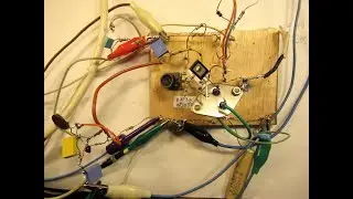
Sometimes the sound is perfect, but on the same time it oscillates on (say) 50 KHz. That is really possible, you can only detect that issue with an oscilloscope. HF oscillations in audio amplifiers are always bad, they can ruin your power transistors at the output of the end-amplifier (to the loudspeaker boxes) due to extreme heating, heat up the power supply, etc. Stopping oscillations in this 2 transistor amlifier is done in 2 ways: changing the bias (working point, with the 22 K potentiometer) and/or change the amplification (turn the 1 K potentiometer in the emitter lead, wiper to ground means less or no amplification).
Also a good remedy: a 470 pF capacitor from the base of the first transistor to ground. When you hear radio stations when using this pre-amplifier: solder a ceramic capacitor of 30 pF or 50 pF between the collector and the base of transistor 1.
All the videos hat I have published on You Tube can be found via my Channel Trailer: Link is
• Radiofun232 on YouTube. Updated month...
In thematic order you can find these video’s under the “comments” section.
Important: to find all the links to the (+/-700) video’s on my YT Channel, select, in the comments section, “NEWEST FIRST”
My books about electronics are available via the website from “Lulu”, search for author “Ko Tilman” there.
https://www.lulu.com/shop/search.ep?k...
There is an important video via which you can buy a document where I give links to many of my video’s, published between 2010 and 2018.
Link is: • Radiofun232: Links to my You Tube vid...
My books are also available via Barnes and Noble and via Amazon.
Regarding all my video’s: I constantly keep them actual, so the original video’s with the most recent information are always on YouTube. That is the source, and search there. When my video’s are reproduced or re-edited on other websites/channels you can not (!) be sure about the original content (=really working electronics) and important adaptations to the circuits.
Be aware of that, I saw on the internet my circuits reproduced in a poor or even not proper way. I can not help that, sorry. Upload 7 march 2019.
BACKGROUND INFORMATION: in modern and old-school (1970-1990) audio amplifiers you often see a backcoupling circuit. This consists often of a resistor going from the end-transistors to somewhere at the input of the first transistor(s). The aim of that resistor is to limit the audio distortion. Only 1 resistor (10 K-500 K) often works very well to fulfill that job and can bring the audio distortion down substantially, to 1 % or even less. Good thing of only a resistor: it is frequency independent, so the distortion reduction works over the whole 20 Hz-20 KHz frequency band; of course: given no other non-linearities in the amplifier circuit. Sometimes this “feedback resistor” is combined (in one or another way, in series or parallel) with a “tiny value” (often ceramic) capacitor, so in the 100 pF-1 N (max. 4N7) range. In that case the R-C combination makes the backcoupling frequency dependent, so the audio amplifier has a kind of boost in a certain audio frequency band (somewhere between 20 Hz and 20 KHz) + there is the advantage of less audio distortion. Feel free to experiment with that concept, when you develop audio (power) amplifiers. In fact not so much can go wrong, the only “risk” is that your audio amplifier can start to oscillate when you connect this R or R-C combination to the “wrong” location (means phase shift or a point of too high amplification) at the first transistors in that (experimental) audio amplifier.
![[Raw, Boring] Four Random Landings](https://images.mixrolikus.cc/video/wacFCUJeWzc)