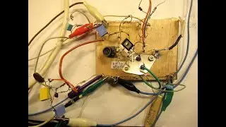
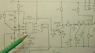
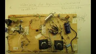
P MOSFET IRF 9504 N drives a high current load and does not get too hot (schematic & demo)
Important correction: I talk about the the 2M2 resistor but in real it is 3M3 (orange-orange-green). Anyway. I am (almost) sure it will also work with that 2M2 resistor.
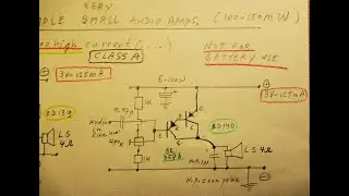
By the way: I stop these series of experiments because the MOSFETS (both P and N types) do not have better properties in power supplies for Audio (music) applications, say between 12 V and 42 Volt. My aim was to make a mains power supply (50/60 Hz) with no hum and a relatively cool series transistor.
But: bringing down the hum to an absolute zero level is surely possible. Many video's about how to do that are on my YT Channel. The MOSFET plays no specific aim or role here, compared to bipolar transistor types.
The better use of a MOSFET is that of a switch, driven constantly by a frequency with a certain input level into the Gate (really, if not constantly it burns can burn out) with a generator on 10 KC-30 KC with a variable duty cycle.
An earlier video about driving MOSFETS via a (say) static (varying) voltage on their GATE (be it a P- MOSFET or an N-MOSFET) and the problems that are raised when doing so (heat, burning out of the MOSFET, while using static voltages in higher power applications, say higher than 18 V and 3 Amp. in this specific way) are here: • Are MOSFETS ideal in power applicatio...
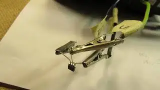
This now published video regards a few experiments that I did during the past days (April 2020). My aim was to drive a high current load (say 1 or more Ampères at say 24 Volt or 30 Volt) between the Drain and Source (Ground) of a MOSFET, while the Ground had to be on “earth/minus”. That is why I used a P MOSFET with its Drain on ground, minus (-).
It worked good, but only with incandescent (filament) lamps and with an Astabile Multivibrator with a variabe duty cycle to (after all) drive a variable current between Source and Gate of the P-MOSFET.
That Astabile Muvib worked in this case on (say) 8 KHz, I tested it further, it also could work on 20 KHz or higher, say with 1 N 5 capacitors) while changing the duty cycle at the same respect, of course. But it got unstabile with smaller caps than 3N3.
There are 3 flaws in the circuit:
A) when you connect a electrolytic capacitor “over” the incandescant lamps the P MOSFET gets directly defective.
B) You will always find (oscilloscope) the frequency of the generator parallel to the load, be it incandescent lamps or whatever. So a no useful circuit to be used as a power supply for (say) an audio amplifier, unless you can go to (say) 50 KHz?
C) The Astabile Multivibrator (generating the driver frequency + the duty cycle) does not want to start when you slowly drive up the voltage to that Muvib. That is why I have drawn a “start” switch in the schematic that suddenly adds 12 V or 18 V or 30 V to the Astabile multivibrator. If so it surely starts via that voltage ”pulse”.
Anyway: there are methods to make that 2 transistor Astabile Muvib start at any time and under any conditions. Advice: do experiments. Key: the “balance” must be taken out of TS 1 and TS 2 while starting at a slowly rising supply voltage; with exact balance, when adding the supply voltage slowly, the Astibile Muvib “locks” itself (=not working).
More about that “not willing to start problem” is here • fail properties from the non stabile ...
More general info about Astabile Muvibs is here • Astabile Multivibrators: how to make ...
My Channel Trailer is here: • Radiofun232 on YouTube. Updated monthly.
There are (some) links to my video’s on YT available on my Channel Trailer in the “comments” section. Select, in the comments section, always “NEWEST FIRST” to get the right overview.
My books about electronics & analog radio technology are available via the website from “LULU”, search for author “Ko Tilman” there.
https://www.lulu.com/shop/search.ep?k...
Some of my books (not all) are available via Barnes and Noble and via Amazon.
But all my books (the complete bunch) are/is available on the website of LULU.
Regarding all my video’s: I constantly keep them actual, so the original video’s with the most recent information are always on YouTube. That is the source, and search there. When my video’s are reproduced or re-edited on other websites/channels you can not (!) be sure about the original content (=really working electronics with real properties for a purpose) and important adaptations to the circuits.
Be aware of that, I saw on the internet my circuits reproduced in a poor or not proper way.
I also found that people probably republish my circuits under phantasy names and/or with phantasy properties, attributing electronic properties to them that they were never made for. Sometimes they want to find gold with them. I take distance from all these fake claims; I cannot help that it happens, sorry. Upload 22 April 2020.