Making a very simple oscilloscope Pt. 4: a basic working HV osc. circuit with an output of 250 V DC
Please read the description/textbox first.
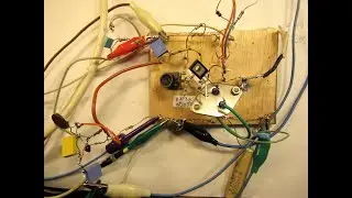
Please note: in this demo the oscilloscope tube DG 7-32 was not used (by purpose) on its nominal Anode-Cathode voltage of 300-400 Volts DC (400 V max).
Further video (20 oct 2022) is here • Making a very simple oscilloscope Pt ... (proper grid connections focus & brightness cf. the datasheet of the DG 7- 32).
Earlier video ( 8 october 2022) is here • Making a very simple oscilloscope Par...
NEXT VIDEO (15 October 2022) is here • Making a very simple oscilloscope Pt ...
The HV oscillator in this new vid (13 oct 2022) only gives out 250 Volts DC. Thus that mean that everything is under-dimensioned?
Yes and no. The tube works properly with this lower Anode-Cathode voltage, but of course there must be/had to be some adaptations regarding the “focus” and the “brightness” grid.
These grids/electrodes are, by the way not “grids” but “tube like” structures, working with equipotential (and other potential) voltages to focus the electron beam.
Important: when you want the brightness grid to be on the maximum negative potential: connect a resistor of 45 K-1M to the cathode grid, to get the situation where the brightness grid can be dipped to the extreme negative of the HV supply.
Because electrons are (in general) negative & can be seen as particles (even as wave forms, btw) these negative charged particles (or a focused beam of them inside this CRT tube) can be/will be deflected by negative charges/fields. Say pinched away (-) or attracted (+).
These fields/charges can be attributed to the horizontal or vertical plates inside the CRT, thus making the dot on the screen (say the electron beam inside the tube) move.
Thus the dot on the screen of a CRT can move to more or less all positions, left-right, up-down, even can move out of the screen (face) of the CRT.
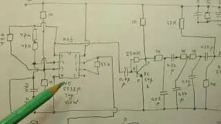
Important to tell regarding this schematic: you can get into the situation where everything works OK (!), HV is there etc. But you don’t see anything on the screen (…)?
Did you do something wrong? No.
Disconnect the electrolytic capacitor (33 uF-400 V) on the secondary of the HV transformer. Reason for S1 in the circuit.
If so you will only have to do with the pure static charges that must be there (pure static!) that make the CRT work: electron beam, deflection, proper positioning of the electrostatic deflection plates, etc.
You will see that dot on the screen again when you disconnect that electrolytic capacitor. That 33 uF worked best in this case/schematic (tested).
When charges “heap up” on the deflection plates: take time. All the static voltage deflection plates (hor-vert) are in a vacuum, so it can take a lot of time before static charges on the deflection plates are flown away, via the air, etc.
Remedy: connect plates with 1 electrode of them via a crocodile clip to earth to discharge them.
To know: In old school TV sets (1940-2010 etc.) the HV oscillator was calculated to work precisely (!) on its best HV output with the normal internal capacitance (inside layer) of the Television tube. Of course with the line frequency, around 16 KC.
Thus: maximum HV out with the CRT tube (its inner side) as “load capacitor” to which the HV was connected.
That was also the reason why often old school CRT television tubes failed after (say) 6-8 years or so: dust heaped up around the CRT, acting as capacitance/resistance, bringing the oscillation frequency of the line oscillator (around 16 KC) down.
Thus bringing the HV on the CRT also down to a situation where the light on the TV tube dimmed, or the tube started to flicker, etc.
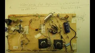
Please note: in the final part of the video I talk about the risk of electric shocks. The risk is this: touching the output of the HV transformer (250 V at 16 KC, paralleled to that is a 33 uF capacitor) with your hand/body can give a not too heavy shock. Please note: hold children and heart patients away.
In a "throw away camera" there is sometimes a flash unit. That is, effectively, more dangerous when you open that camera and get in contact with that flash capacitor.
My You Tube channel trailer is here: • Radiofun232 on YouTube. Updated month... When you search, search always “NEWEST FIRST” to get the right overview. You can also search via the “looking glass” on my Channel trailer via keywords like ”audio”, “radio”, “amplifier”, “filter”, “Shortwave”, “transistor”, “FET”, “oscillator”, “generator”, “switch”, “schmitt trigger” etc; so the electronic subject you are interested in.
My books about electronics & analog radio technology are available via the website of "LULU”, search for author “Ko Tilman” there.
https://www.lulu.com/search?adult_aud...
I keep all my YT videos constant actual, so the original video’s with the most recent information are always on YouTube. Search there, and avoid my circuits that are republished, re-arranged etc.
I cannot help that these things happen. Upload 13 oktober 2022.


![[ FREE ]](https://images.mixrolikus.cc/video/QlPtNxxrtB8)