Table microphone with audio limiter first experimental results: 741 Opamp & NPN transistors (VLOG)
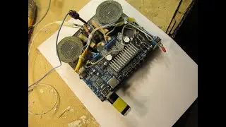
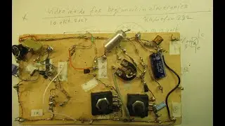
VLOG (nothing more). First experimental setup to develop a table microphone (say to be connected to a computer or an end amplifier) with an “audio limiter” circuit, that presses the microphone signal down (to an acceptable other level) when the audio is too fierce.
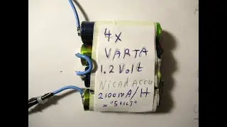
By the way: supported by a 9 V battery or a separate hum free power supply out of the mains, be it 110 V or 230 V 50 Hertz or 60 Hertz (still to be developed ).
It is not fed via a phantome power supply or via the (5V) out of the computer (say USB, or microphone input). Perhaps it is interesting to show how you can solve certain analog/audio electronic problems (in fact: not complicated). That is the aim of this VLOG.
Correction to the video: on 1.56 I say “the 2N007” transistor but of course it must be the 2N117 transistor (like it is written!).
Of course the circuit must have less distortion as possible) during (say) 1 second-3 seconds (delay time).
In audio we know this as the “attack” and “decay” time of an (active/transistor or electronically driven) microphone. The attack and decay times are often often adjustable, their settings depend on on where (room conditions) and how (music/speech/discussion) the microphone is used, or the expected use: strong or weak audio signals (voices etc.).
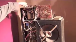
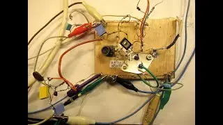
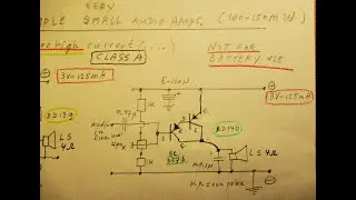
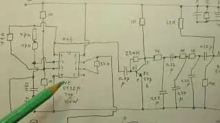
The circuit is still in a primature state, but perhaps it is interesting to show the principles that I used for developing. The first transistor has a capacitor (condensor) microphone at its base, the used transistor is (now, can change) set to its maximum amplification (circuit in my books and in earlier YT video’s). I will try to bring the supply voltage down in relation to the noise, generated by the transistors, amplifying the microphone signal.
Such a first transistor (or FET), be it HF (radio) or AF (audio) is a critical factor regarding noise. A reason why in radio telescopes the LNB is cooled (perhaps to almost zero degrees, I don’t know that exactly). It limits the noise (temperature of the first transistor). When you are interested in “noise versus temperature”: read e.g. articles about the Boltzmann constant on the www.
The Opamp (741) is here to drive a Darlington (2 x BC 547 b) that is responsible to charge the capacitor (of 470 uF). That capacitor dumps its (+) charge into the base of a BC 547 b NPN transistor, so that it starts to conduct (during a certain time) and shortcuts the potentiometer (4K7) responsible for the input level to the base of the second transistor stage (grounded emitter, also a BC 547 b).
AC and DC are everywhere separated, where necessary. Anyway: the first results are encouraging, but there is still something to do.
And my aim is (always) that everyone interested in electronics/audio/radio must be able to copy the circuit with as cheap components as possible.
At the moment the circuit surely works and there is almost no distortion when the microphone gets a (too) fierce signal, but the process of going back to more amplification is “limited” in this way: there is no return to a very “fierce” amplification, after activating the limiter (attack/decay). That is, as a first result, good and useful, but I want to get more/better control in this process: attack/decay/returning to amplification level x.
My You Tube channel trailer is here: • Radiofun232 on YouTube. Updated month...
There are (some) links to my video’s on YT available on my Channel Trailer in the “comments” section. Select, in the comments section, always “NEWEST FIRST” to get the right overview. You can also search via the “looking glass” via keywords like ”audio”, “radio”, “amplifier”, “filter”, “Shortwave”, “transistor”, “FET”, “oscillator”, “generator”, “switch”, “schmitt trigger” etc; so the electronic subject you are interested in.
My books about electronics & analog radio technology are available via the website from “LULU”, search for author “Ko Tilman” there.
https://www.lulu.com/search?adult_aud...
Some of my books (not all) are available via Barnes and Noble and via Amazon.
But all my books (the complete bunch) are/is available on the website of LULU.
Regarding all my video’s: I constantly keep them actual, so the original video’s with the most recent information are always on YouTube. That is the source, and search there. When my video’s are reproduced or re-edited on other websites/channels you can not (!) be sure about the original content (=really working electronics with real properties for a purpose) and important adaptations to the circuits.
Be aware of that, I saw on the internet my circuits reproduced in a poor or not proper way.
I also found that people probably republish my circuits under phantasy names and/or with phantasy properties, attributing electronic properties to them that they were never made for, so phantasy properties. Sometimes they want to find gold with them. I take distance from all these fake claims; I cannot help that it happens, sorry. Upload 18 august 2020.
![[Raw, Boring] Four Random Landings](https://images.mixrolikus.cc/video/wacFCUJeWzc)