Rebuilding/downgrading a high Q Farnell sine wave generator to a simpe circuit 100KC - 10MC (VLOG 1)
VLOG. Please read the description/textbox first. My beautiful 1 Hertz-1 MegaHertz Farnell sine wave generator was damaged during experiments developing the very simple oscilloscope (20Hertz-20 KHZ).
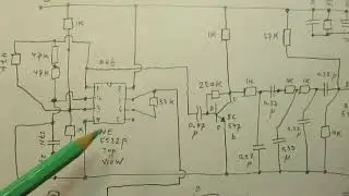
BEST results with 1 FET BF 256 A, working as a pure sine wave oscillator from 130 KC - 8 MC (tested 15 Feb 2023) is in this video + schematic:
• Sine wave oscillator for 120 KC - 8 M...
The video series of the oscilloscope development is also on my YT Channel.
Link to the final video (5 december 2022) of that very simple oscilloscope is here: • Making a very simple oscilloscope Pt....
(approx. 8 earlier videos are there about this oscilloscope project)
I am sure that a high voltage out of the experiments developing this oscilloscope entered the output pin of the Farnell Sine Wave Generator. Made to work between 10 Hertz and 1 MC (1 MHz).
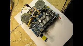
I found 1 burned out resistor. Anyway: repairing was not an option (too complicated), so I chose to use the “frame” of that Farnell unit to develop a sine wave generator with coils, going from (first idea) 100 KC-10 MC or 12 MC. Maximum frequency has to be found out experimentally. Perhaps it all will work on higher frequencies”? I don’t know, that is the advantage and interesting thing. It is “downgrading” or in terms of frequency range "upgrading" though the frequency stabily will be the looser.
Reason why this all can work: the high quality tuning capacitor inside of that Farnell unit, say 2 x 500 pF + the high quality dial that was used.
Of course the dial setting will never correspond any longer in combination with my simple “hobby” circuit, anyway.
Perhaps one of the coil/dial settings will work/fit/correspond, and that is also good. When I am lucky.
The most important property of the high quality dial is that it makes precise tuning to a certain frequency possible.
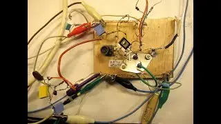
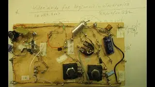
I scraped the board (on the copper clad side) completely clean with an angle grinder, removed all the components, so now there is room to make a new build up.
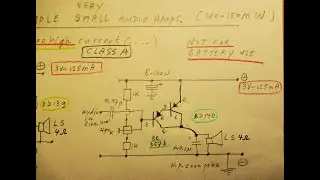
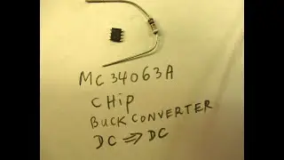
I will use this (as a first idea) FET oscillator. It can work from 400 KC up to 15 MC.
Link: • FET test oscillator sine wave with ve...
Also want to put in an AM modulation unit on 1000 Hertz with variable modulation depth, say going from 10 % to max. 50 % AM modulation. That is usable for testing standard AM coils and ceramic filters on 430-480 KC. With the help of a simple AM diode detector.
This is only a VLOG, showing some first idea’s about a setup, but also with practical information when you want to work with coils and want to use simple switches, made for audio purposes, in radio/Shortwave circuits. They are usable, up to max. 15 MC.
When I say “damaging will not happen any longer” I mean: this 100 KC-10 MC or 12 MC oscillator will be so simple (1 FET transistor and 1 Buffer transistor + a 2 transistor Muvib circuit on 1 KHZ) that damaging the circuit due to rough handling will be (more or less) impossible, especially in the setting without a DC OUT.
My You Tube channel trailer is here: • Radiofun232 on YouTube. Updated month... When you search, search always “NEWEST FIRST” to get the right overview.
You can also search via the “looking glass” on my Channel trailer via keywords like ”audio”, “radio”, “amplifier”, “filter”, “Shortwave”, “transistor”, “FET”, “oscillator”, “generator”, “switch”, “schmitt trigger” etc; so the electronic subject you are interested in.
My books about electronics & analog radio technology are available via the website of "LULU”, search for author “Ko Tilman” there.
https://www.lulu.com/search?adult_aud...
I keep all my YT videos constant actual, so the original video’s with the most recent information are always on YouTube. Search there, and avoid my circuits that are republished, re-arranged, re-edited on other websites, giving not probable re-wiring, etc. Some persons try to find gold via my circuits. I take distance from all these fake claims. I cannot help that these things happen. Upload 3 February 2023.


![CORRUPTION TIME [0.6.0] [Incutia] باللغة العربية PT ESPAÑOL ANDROID Y PC](https://images.mixrolikus.cc/video/fgo4c0crog0)