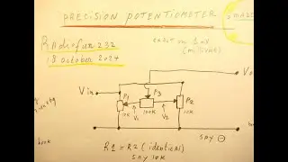
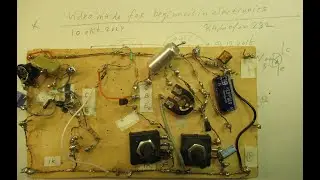
Sine wave to square wave converter 1 KC-1 MC with 2 transistors and 2 potmeters: schematic & demo.
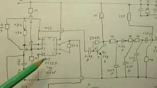
Please read the description/textbox first. Schematic of an electronic circuit that can change sine waves into square waves in the frequency band of 1 KC- to 1 MC (1 Million Hertz), with a good quality (read pure) square wave.
Important: you have to align the 2 (or 3) potentiometers to get a good waveform when tuning in this broad frequency band when you need a certain duty cycle, say a 50-50 wave, or a 20-50 wave, anyway.
The circuit showed in this video does not work below 700 Hertz. I indicated it as 1 KC as the lowest frequency, I did not want to show too high expectations...., but when you test it it can go to low as 700 Hertz. With some setting of the 2 (or 3) potentiometers.
Earlier video (a week ago or so) was the "pulse shaper". It did not work on such a high frequency. Link is here • Pulse shaper (sine wave to kind of sq...
Input sensitivity of the circuit now (22 august 2022, sine waves in) is between 0,2 V (200 mV) and 0,9 V (900 mV). Input level is critical for a good square wave (watch the video).
The circuit can be supplied with voltages between 12 V and 18 Volt. So it is, in a kind of way, universal.
You can, with this circuit, e.g. use fixed value resistors to fix the duty cycle (=square wave form) to a certain value for a certain electronic purpose.
Thus driving another circuit between 1 KC and 1 MC, via square waves with a certain duty cycle. At sine wave input levels (1 KC-1MC) between 200 mV and 900 mV. Could be enough.
Fixing this transistor circuit to a certain frequency and duty cycle is very easy to do by using fixed value resistors instead of the 2 essential potentiometers in this circuit (the 5K and the 25 K that do their jobs), after some experiments regarding the frequency and the duty cycle that you want/need.
For electronic circuits that need an always stable waveform, use a 7812 (= a 12 positive Volt stabilizer) that will fix /hold the supply voltage to this 2 transistor circuit to an exact level and thus “freeze” the waveforms when the fixed value resistors or potentiometers are set to the point where you have the frequency and duty cycle that you want/need for a certain electronic application, say a transistor driver or so.
My You Tube channel trailer is here: • Radiofun232 on YouTube. Updated month... When you search, search always “NEWEST FIRST” to get the right overview. You can also search via the “looking glass” on my Channel trailer via keywords like ”audio”, “radio”, “amplifier”, “filter”, “Shortwave”, “transistor”, “FET”, “oscillator”, “generator”, “switch”, “schmitt trigger” etc; so the electronic subject you are interested in.
My books about electronics & analog radio technology are available via the website of "LULU”, search for author “Ko Tilman” there.
https://www.lulu.com/search?adult_aud...
I keep all my YT videos constant actual, so the original video’s with the most recent information are always on YouTube. Search there, and avoid my circuits that are republished, re-arranged, re-edited on other websites, giving not probable re-wiring, etc. Some persons try to find gold via my circuits. I take distance from all these fake claims. I cannot help that these things happen. Upload 22 August 2022.
First video where I showed the basics of this electronic setup (sinewaves to square waves) is here (15 september 2011, time goes fast)
• change a sine wave into a square wave...