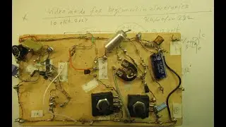
Change a square wave into sine wave on very low frequencies -proof of principle circuit-
Video proof of principle circuit about how to change square waves on very low frequencies, say between 10 Hertz and 100 Hertz into sine waves.
Link to LF square wave oscillator + schematic used in this experiment • Square wave oscillator for very low freque...
Very good & easy squarewave oscillator can be made with a TL 071 Opamp, circuit is here:
• Perfect square wave oscillator schematic &...
Please note: the signal that I sent into the 4-pole filter has an AC level from approximately 12 Volt. In an earlier video I showed how I made that square wave oscillator for low frequencies 0,01 Hz-800 Hz.
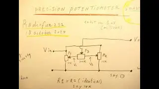
IMPORTANT: With 10 K resistors instead of 1 K resistors you have a perfect sine waveform between 3 Hertz and 14 Hertz -tested-.
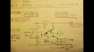
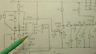
It is very easy to change a square wave to a sine wave with the help of a 3 pole or 4 pole LC filter. In the low audio range (say max 1000 Hertz) the resistors in transistor circuits must be between 1 K and 10 K and the caps must be between 1 uF non polar and 470 N (or 100 N = 0,1 uF for max 1000 Hertz) non polar.
Always use in principle the same R and C values in each node - pole- of the filter. Small deviations from the standard used capacitances and resistances in general don’t have an effect on the waveform.
Please note: the 3 pole or 4 pole filter is a tuned circuit that, at its best, performs on a specific frequency though on small deviations from that central frequency it keeps working good. So don’t worry.
And when you go to higher frequencies 1000 Hz and higher this frequency deviation where it all stays working gets higher c.q. more broad. So this filter 3 pole or 4 pole gets working better on higher frequencies, in terms of the broadness of the frequency band where a good sine wave is produced out of a square wave from the same frequency.
With an oscilloscope, a frequency counter these filters in the low frequency range can all be figured out very easily. Use 100 N caps =0,1 uF to go to the frequency range 200 Hz-600/800 Hertz.
Use 3 pole filters or 4 pole filters. Every time a pole is added R-C the waveform will be more pure in principle-, but the maximum is -in general & practice 4 poles, because each pole brings the energy down. Important: the output level in 3 or 4 pole R-C filters diminishes very substantially. So 12 V AC in can mean 1 V AC or less…. out. Anyway: a simple AC audio pre-amplifier can lift that output volume up again.
All the videos hat I have published on You Tube can be found via my Channel Trailer: Link is
• Radiofun232 on YouTube. Updated monthly.
In thematic order you can find these video’s under the “comments” section.
IMPORTANT: to find all the links to the +/-700 video’s on my YT Channel, select, in the comments section, “NEWEST FIRST”
My books about electronics are available via the website from “Lulu”, search for author “Ko Tilman” there.
Link is https://www.lulu.com/shop/search.ep?k...
My books are also available via Barnes and Noble and via Amazon.
Regarding all my video’s: I constantly keep them actual, so the original video’s with the most recent information are always on YouTube. That is the source, and search there. When my video’s are reproduced or re-edited on other websites/channels you can not be sure about the original content =really working electronics and important adaptations to the circuits.
Be aware of that, I saw on the internet many of my circuits reproduced in a poor or even not proper way. I can not help that, sorry. Upload 19 june 2018.